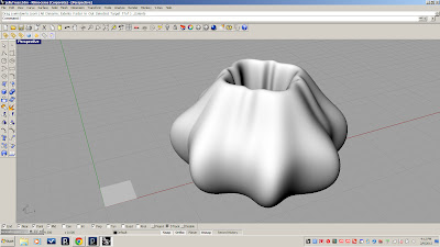
For this tutorial we will be developing a panel system for the superformula towers we made in the previous session. This tutorial is heavily influenced by the parametric truss tutorial by David Fano which can be found at http://designreform.net/2009/07/rhino-grasshopper-parametric-truss .
To begin we will create a blank rectangular surface to test our definition before extrapolating it onto our superformula towers.
The next step is to explode the surface into it's base components using bRep Components. By connecting the vertex output into a set of 4 List Item nodes, we are able to isolate individual vertices.
We will also want to find the center of my surface patch for the pattern I am trying to produce, so we will connect the face output of our bRep Component to an area(bRep) node. This will give us the area centroid. Since we will eventually be generating this on a curved surface we can use the surface Closest Point tool to find a project point for our centroid. Once I have that point located, I can link my Vertices and center point to PolyLine nodes using shift select. It is important to link the vertices in the order you want them in the polyLine. Also the PolyLine boolean C value should be set to "true" for closed polyLines.
Next I will input the vertices into cvCurve nodes in the same order to produce interior curves for my panel sections. The P value should be set to "true" to make the curves closed.
In order to adjust the scale of the holes in panels, I am going to output my curve to a scale node. In order to insure that it is scaling around its centroid I also output the curve to an area node, connecting it's centroid output to the origin of the scale node. I also attach a single slider to the factor inputs on all four scale nodes to modulate the hole size.
Once I have my curves scaled, I connect the corresponding polyLines and scaled outputs to a loft node. Under options, I have set the align curves option on to insure a clean loft.
Now that we have our basic panel designed, we need to divide our target surface into quads so that we can use it in the same was as our base rectangle. To do this we will link our surface into a divide domain2 node as the input. Then using two sliders set to integers, we set the number of divisions in each direction (u,v). We can then connect our surface and divisions to an isoTrim node which will output 4 edged divisions of our surface.
Finally, we connect the output from our isoTrim to the input of our original brepComponent (replacing the rectangle) and we have our final panelized geometry.


No comments:
Post a Comment